|
modm API documentation
|
#include <modm/platform/adc/adc.hpp>
Public Types | |
| enum | Channel : uint8_t { In0 = 0, In1 = 1, In2 = 2, In3 = 3, In4 = 4, In5 = 5, In6 = 6, In7 = 7, In8 = 8, In9 = 9, In10 = 10, In11 = 11, In12 = 12, In13 = 13, In14 = 14, In15 = 15, Temperature = 16, InternalReference = 17, Battery = 18 } |
| enum | ChannelMask : uint32_t { In0 = (1u << 0), In1 = (1u << 1), In2 = (1u << 2), In3 = (1u << 3), In4 = (1u << 4), In5 = (1u << 5), In6 = (1u << 6), In7 = (1u << 7), In8 = (1u << 8), In9 = (1u << 9), In10 = (1u << 10), In11 = (1u << 11), In12 = (1u << 12), In13 = (1u << 13), In14 = (1u << 14), In15 = (1u << 15), Temperature = (1u << 16), InternalReference = (1u << 17), Battery = (1u << 18) } |
| enum | ClockMode { Synchronous, Asynchronous } |
| enum | SampleTime : uint8_t { Cycles1_5 = 0b000, SampleTime::Cycles7_5 = 0b001, SampleTime::Cycles13_5 = 0b010, SampleTime::Cycles28_5 = 0b011, SampleTime::Cycles41_5 = 0b100, SampleTime::Cycles55_5 = 0b101, SampleTime::Cycles71_5 = 0b110, SampleTime::Cycles239_5 = 0b111 } |
| enum | Resolution : uint8_t { Bits12 = 0, Bits10 = ADC_CFGR1_RES_0, Bits8 = ADC_CFGR1_RES_1, Bits6 = ADC_CFGR1_RES_0 | ADC_CFGR1_RES_1 } |
| enum | Interrupt : uint32_t { Ready = ADC_IER_ADRDYIE, EndOfSampling = ADC_IER_EOSMPIE, EndOfConversion = ADC_IER_EOCIE, EndOfSequence = ADC_IER_EOSIE, Overrun = ADC_IER_OVRIE, AnalogWatchdog = ADC_IER_AWD1IE } |
| enum | InterruptFlag : uint32_t { Ready = ADC_ISR_ADRDY, EndOfSampling = ADC_ISR_EOSMP, EndOfConversion = ADC_ISR_EOC, EndOfSequence = ADC_ISR_EOS, Overrun = ADC_ISR_OVR, AnalogWatchdog = ADC_ISR_AWD1, All = ADC_ISR_ADRDY | ADC_ISR_EOSMP | ADC_ISR_EOC | ADC_ISR_EOS | ADC_ISR_OVR | ADC_ISR_AWD1 } |
| enum | DmaMode : uint32_t { Disabled = 0, OneShot = ADC_CFGR1_DMAEN, Circular = ADC_CFGR1_DMACFG | ADC_CFGR1_DMAEN, Mask = Circular } |
| enum | ExternalTriggerPolarity { NoTriggerDetection = 0x0u, RisingEdge = 0x1u, FallingEdge = 0x2u, RisingAndFallingEdge = 0x3u } |
| enum | RegularConversionExternalTrigger { Event0 = 0x0u, Event1 = 0x1u, Event2 = 0x2u, Event3 = 0x3u, Event4 = 0x4u, Event5 = 0x5u, Event6 = 0x6u, Event7 = 0x7u } |
Public Member Functions | |
| MODM_FLAGS32 (ChannelMask) | |
| MODM_FLAGS32 (Interrupt) | |
| MODM_FLAGS32 (InterruptFlag) | |
Static Public Member Functions | |
| template<class... Signals> | |
| static void | connect () |
| template<class SystemClock , ClockMode mode, frequency_t frequency = MHz(1), percent_t tolerance = pct(10)> | |
| static void | initialize () |
| static void | enable () |
| static void | disable () |
| static void | setAutoOffMode (bool enable) |
| static void | setWaitMode (bool enable) |
| static bool | isReady () |
| static uint16_t | calibrate () |
| static void | startConversion () |
| static void | stopConversion () |
| static bool | isConversionFinished () |
| static uint16_t | getValue () |
| static uint16_t | readChannel (Channel channel) |
| static uint16_t | readInternalVoltageReference () |
| Reads the calibrated Internal Reference Voltage in mV. | |
| static int16_t | readTemperature (uint16_t Vref) |
| Reads the calibrated temperature in degree Celsius. | |
| static void | setResolution (Resolution resolution) |
| static void | setLeftAdjustResult () |
| static void | setRightAdjustResult () |
| static bool | setChannel (Channel channel) |
| static void | setChannels (ChannelMask_t channels) |
| template<typename... Gpios> | |
| static consteval ChannelMask_t | channelMaskFromPins () |
| static void | clearChannel (Channel channel) |
| template<class Gpio > | |
| static bool | setPinChannel () |
| Setting the channel for a Pin. | |
| template<class Gpio > | |
| static constexpr Channel | getPinChannel () |
| Get the channel for a Pin. | |
| template<class Gpio > | |
| static uint16_t | readPinChannel () |
| static void | setSampleTime (SampleTime sampleTime) |
| static void | enableFreeRunningMode () |
| static void | disableFreeRunningMode () |
| static void | enableInterruptVector (uint32_t priority, bool enable=true) |
| static void | enableInterrupt (Interrupt_t interrupt) |
| static void | disableInterrupt (Interrupt_t interrupt) |
| static InterruptFlag_t | getInterruptFlags () |
| static void | acknowledgeInterruptFlags (InterruptFlag_t flags) |
| static uintptr_t | getDataRegisterAddress () |
| static void | enableRegularConversionExternalTrigger (ExternalTriggerPolarity externalTriggerPolarity, RegularConversionExternalTrigger regularConversionExternalTrigger) |
| static void | setDmaMode (DmaMode mode) |
| static bool | getAdcEnabled () |
| static void | enableInternalChannel (Channel channel) |
| static void | acknowledgeInterruptFlag () |
| template<uint64_t available, uint64_t requested, percent_t tolerance> | |
| static void | assertBaudrateInTolerance () |
| template<double available, double requested, percent_t tolerance> | |
| static void | assertDurationInTolerance () |
| static void | configurePurpose () |
| configures a peripheral for a specific purpose | |
| static uint8_t | getChannel () |
| static bool | getInterruptFlag () |
| Read an interrupt flag. | |
| static void | getParameter () |
| returns a parameter | |
| static void | setParameter () |
| sets a parameter | |
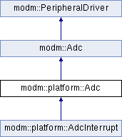
Analog/Digital-Converter module (ADC1).
The 12-bit ADC is a successive approximation analog-to-digital converter. It has up to 19 multiplexed channels allowing it measure signals from 16 external and three internal sources. The result of the ADC is stored in a left-aligned or right-aligned 16-bit data register.
This API is designed for the internal ADCs of STM32F0x1/STM32F0x2/STM32F0x8
Regular conversion external trigger sources
The source mapped to each event varies per controller family, refer to the ADC external trigger section in the reference manual of your controller for more information
|
strong |
|
inheritedstatic |
Acknowledge an interrupt flag.
We use acknowledge here, since it describes the intention rather than the actual implementation.
|
inheritedinlinestatic |
Since baudrates are usually generated by prescaling a system clock, only several distinct values can be generated. This method checks if the user requested baudrate is within error tolerance of the system achievable baudrate.
|
inheritedstatic |
|
static |
|
inlinestatic |
Returns true if the ADRDY bit of the ISR is set
|
inlinestatic |
Analog channel selection.
This not for scan mode. The number of channels will be set to 1, the channel selected and the corresponding pin will be set to analog input. If the the channel is modified during a conversion, the current conversion is reset and a new start pulse is sent to the ADC to convert the new chosen channnel / group of channels.
| channel | The channel which shall be read. |
|
inlinestatic |
Set channel scan sequence mask. All selected channels will be converted sequentially starting from the lowest.
| channels | Mask of channels to convert |
|
inlinestatic |
Configure DMA mode (disabled, one-shot or circular)
In one-shot mode DMA requests are disabled at the end of the DMA transfer. If circular mode is selected request are being generated as long as conversions are performed.
 1.4.2
1.4.2 
